
Pressure Vessel Thermal Analysis: A Practical FE Workflow

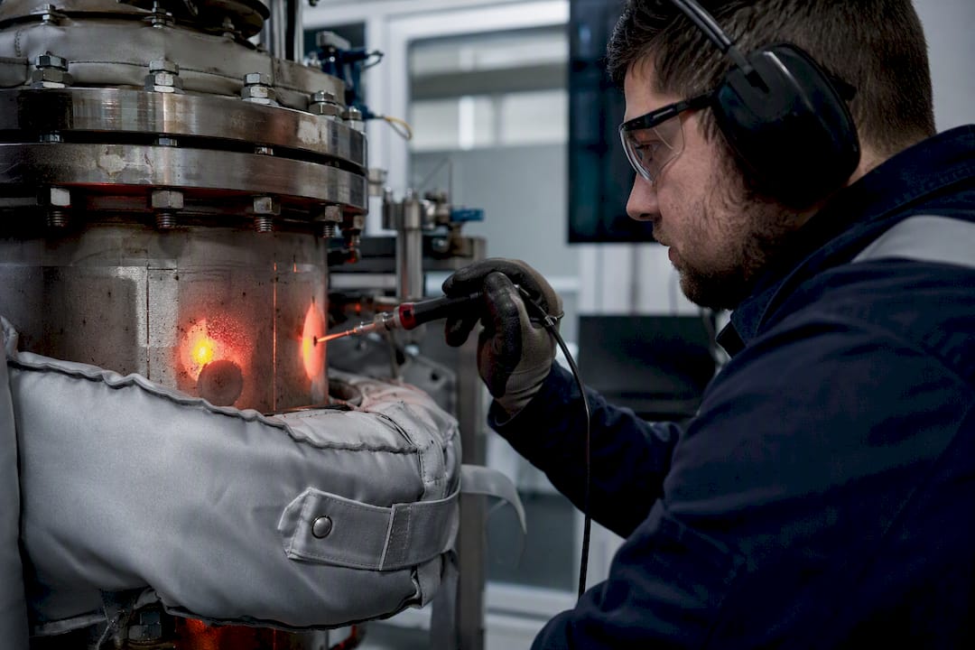
The recommended approach for pressure vessel thermal analysis is a sequentially coupled finite-element workflow: run a steady-state solution when a stable initial condition matters, follow it with transient thermal analysis for time-dependent loads, then map the resulting nodal temperatures onto the structural mesh for stress evaluation. Validate every result against mesh convergence and a spot analytical check before you trust it for design or assessment.
A well-documented transient FEA study on a vertical pressure vessel reported a 2.65% fractional error against an analytical solution and a Grid Convergence Index of 0.073, which is the benchmark to aim for when you report mesh independence.
Before you open your preprocessor, lock down these steps:
Choose steady-state, transient, or both, based on how fast the thermal load actually changes.
Build the mesh with through-thickness resolution sufficient to capture the gradient, not just the average temperature.
Map temperatures to the structural model without smoothing away hot spots near nozzles and welds.
Categorize stresses (membrane, bending, peaking) per ASME Section VIII before comparing to allowables.
Jewlztech’s thermal analysis toolkit automates several of these steps for engineers who want a faster path to a validated result.
Key Takeaways
A validated, sequentially coupled FE thermal-to-structural workflow, checked against mesh convergence and ASME stress categorization, is the most defensible path to a pressure vessel thermal analysis that survives a code review.
Point | Details |
Sequence solvers correctly | Run steady-state thermal if needed, then transient thermal, then map temperatures into the structural model. |
Validate with GCI | A published study reported a GCI of 0.073 and 2.65% fractional error against analytical results, a useful benchmark. |
Categorize stress per ASME | Extract membrane, bending, and peak stress at inner, mid, and outer wall positions before comparing to allowables. |
Watch jacket and fouling assumptions | Film coefficients, fouling factors, and jacket type all shift heat duty significantly over service life. |
Use Jewlztech to accelerate setup | The thermal analysis toolkit automates the transient solve, material lookup, and temperature export steps in this workflow. |
Table of Contents
FE Workflow: Preprocessing, Solution Sequencing, and Postprocessing for Thermal-Stress Analysis
Modeling Heat-Transfer Boundary Conditions and Jacketed Vessels
Transient vs Steady-State Thermal Analysis: Time Stepping and Solver Choices
Mapping Temperatures to Structural Analysis and Stress Categorization (DBA vs DBR)
When and Why to Run a Thermal Analysis on a Pressure Vessel
Not every vessel needs a thermal-stress study. Skip it for slow, near-isothermal service and you’re probably fine relying on design-by-rule margins. But certain operating conditions change that calculus fast: cooldown and heat-up transients, cryogenic loading, rapid temperature swings during startup or upset conditions, cyclic thermal loading from batch processes, and jacketed heating or cooling where the shell and jacket see very different temperatures at the same time.
Each of these scenarios drives thermal gradients through the wall thickness, and gradients generate secondary stresses independent of pressure. Left unchecked, they contribute to:
Thermal ratcheting under repeated cycles.
Fatigue cracking at geometric discontinuities.
Stress intensification at welds and nozzle junctions, where local stiffness mismatches amplify the gradient’s effect.
This is exactly where ASME’s design-by-analysis philosophy earns its keep over design-by-rule conservatism. DBR handles simple geometries under steady loads reasonably well, but it wasn’t built to capture transient thermal gradients at a nozzle blend radius. DBA was.
FE Workflow: Preprocessing, Solution Sequencing, and Postprocessing for Thermal-Stress Analysis
Getting a thermal-stress model right starts before you mesh anything. Here’s the sequence that tends to hold up under review.
Pick your geometry representation. Axisymmetric models handle most cylindrical shells and heads efficiently; reserve full 3D for asymmetric nozzles, support saddles, or jacket inlets where the temperature field genuinely varies around the circumference.
Mesh with intent. Resolve at least four to six elements through the wall thickness in regions where the gradient matters, and refine locally at nozzle-to-shell junctions, weld toes, and jacket connections. Use quadratic solid or shell elements for thermal conduction paired with matching structural elements. Coarse meshes elsewhere save solve time without hurting accuracy.
Assign temperature-dependent material properties. Conductivity, specific heat, and thermal expansion all shift meaningfully across a few hundred degrees. Elastic properties should follow suit, and if you’re near creep-active temperatures or cycling into plastic strain, bring in a plasticity or creep model rather than assuming linear elastic behavior throughout.
Sequence the solvers. Run steady-state thermal first if you need a realistic starting temperature field, then switch to transient thermal for the actual event, export the nodal temperature history, and import it as a thermal load into the structural model. This is a sequentially coupled approach, not a fully coupled thermo-mechanical solve, and it’s the standard practice for most pressure vessel work.
Postprocess for the metrics ASME actually checks. Extract stress through the wall at inner, near-inner, mid-wall, near-outer, and outer positions, then linearize to get membrane and bending components at the sections that matter.
Pro Tip: Run your structural model with both the peak transient temperature field and an intermediate time step. The peak thermal gradient and the peak thermal stress rarely occur at the same instant.
Modeling Heat-Transfer Boundary Conditions and Jacketed Vessels
Your boundary conditions determine whether the thermal solution means anything. Convection is usually represented with a film coefficient, and where you don’t have test data, correlations like Sieder-Tate give a reasonable starting estimate for forced convection in piping and jacket annuli. For more complex jacket geometries, a CFD estimate of the film coefficient beats a generic correlation.
Jacket type changes the heat transfer picture substantially. Half-pipe jackets boost velocity and turbulence, which raises the film coefficient but adds fabrication complexity. Dimple jackets let you run thinner jacket walls under higher pressure while adding stiffening ribs the shell can use structurally, a detail worth knowing when comparing jacket configurations for a new design.
A few practical points that catch people out:
Fouling factors erode overall U significantly over service life; don’t model day-one conditions and call it conservative.
Pick the film temperature at the actual bulk fluid condition, not an assumed average, especially for steam versus thermal oil services where properties diverge sharply.
Use LMTD to back into an equivalent heat flux or film boundary condition when you’re not resolving the fluid domain directly.
Reserve full conjugate heat transfer (solid and fluid solved together) for cases where the film coefficient itself is uncertain or highly non-uniform, like a nozzle inlet jet.
Transient vs Steady-State Thermal Analysis: Time Stepping and Solver Choices
Run transient analysis whenever the temperature change happens on a timescale comparable to, or faster than, the wall’s own thermal diffusion time. A thick-walled reactor vessel cooling over two hours, for instance, can develop a meaningful through-wall gradient even though two hours sounds slow. One documented transient example modeled a reactor pressure vessel cooling from 320°C to 282°C over two hours, using distinct film coefficients for the internal water and external air sides of roughly 580 W/m²°C and 28 W/m²°C respectively, which shows how differently each boundary behaves.
Time-step selection should resolve the diffusion front through the thickness, not just satisfy a generic stability rule. Practical guidance:
Start conservative, then use automatic time stepping where your solver supports it to speed up slow-changing phases.
Refine the mesh or the time step, or both, near steep gradients using adaptive remeshing, since a fixed mesh sized for the initial condition can miss a sharpening front later in the transient.
For quick screening, a 1D through-wall analytical or reduced-order check can tell you whether a full 3D transient is even warranted before you commit solver time to it.
Mapping Temperatures to Structural Analysis and Stress Categorization (DBA vs DBR)
Once you have a transient temperature history, mapping it onto the structural mesh is where accuracy either survives or quietly disappears. Interpolation between dissimilar meshes can smooth over the exact gradient spike you built the fine mesh to capture, so match node locations at critical sections wherever the pipeline allows it, and verify by spot-checking peak temperatures before and after the map.
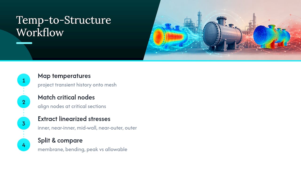
From there, ASME-style stress categorization takes over. You extract linearized stress at the inner, near-inner, mid-wall, near-outer, and outer positions, then split the result into membrane, bending, and peak (local/discontinuity) components, each compared against a different allowable per ASME’s design-by-analysis rules.
This is also where DBA earns its reputation. Reported studies show DBA can support allowable pressures roughly 2.3 to 3 times higher than the equivalent design-by-rule case, depending on the code edition and material involved. That margin only holds up when the FE model backing it is properly validated and the inspection plan matches the analysis assumptions.
Validation, Verification, and Common Numerical Checks
Skip validation and even a beautifully meshed model is just a guess with decimal places. Run these checks before any result goes into a design report:
Mesh-independence study. Solve the same problem at two or three mesh densities and compute the Grid Convergence Index. A GCI in the low single digits, similar to the 0.073 reported in a published vertical vessel validation, signals the solution has stopped changing meaningfully with further refinement.
Analytical spot check. Compare a simplified section, often a thin-wall or 1D radial case, against a closed-form solution. That same study found a 2.65% fractional error between its transient FEA and the analytical benchmark, a useful target range for your own sanity checks.
Transient error tracking. Watch solver error indicators through the run, since a mesh that was fine at the initial steady state can become under-resolved once a steep front develops, which affects both the thermal and downstream structural results.
Practical Tips, Common Pitfalls, and Mitigation Strategies
A few recurring mistakes separate a defensible model from one that gets challenged in a design review.
Don’t over-smooth the temperature map at nozzle and weld locations. Averaging away a local hot spot erases the exact feature you built a fine mesh to find.
Check contact and gap conductance definitions carefully. A contact pair set to the wrong conductance value can redirect heat through a path that doesn’t exist in the real vessel.
Watch for thermal ratcheting under repeated cycles, and where cyclic loading is expected, run an incremental elastic-plastic check rather than relying on a single elastic pass, since transient thermal gradients are a known driver of ratcheting behavior.
Document every assumption. Film coefficients, fouling factors, mesh density criteria, and boundary condition sources should all be traceable for a code audit.
Pro Tip: Keep a one-page assumptions log alongside every model file. Six months later, when someone questions your fouling factor, you’ll want the answer in thirty seconds, not thirty minutes of digging through old emails.
What Actually Moves the Needle in This Workflow
Most thermal-stress models fail not because the math is wrong, but because someone skipped a boundary condition sanity check or trusted a coarse mesh near a nozzle. The sequentially coupled approach outlined here isn’t exotic. It’s standard practice, and the ABS/Eagle guidance on cryogenic tanks follows nearly the same sequence: FE heat transfer, then thermal loads, then FE structural evaluation.
Jewlztech’s toolkit is built around that exact sequence. The transient thermal solver, temperature-dependent material database, and cryogenic boil-off simulator each map to a specific step above, and the export function that hands nodal temperatures to a structural model saves the awkward manual translation step that trips up a lot of first attempts. For worked examples, the pressure vessel stress analysis guide and the cryogenic simulator walk through both the setup and the postprocessing in detail.
— Joel
Try the Workflow Without Building It From Scratch
Setting up a sequentially coupled thermal-to-structural model from a blank solver session takes real time, even for engineers who know the workflow cold. Jewlztech’s thermal analysis toolkit is built around that exact sequence: a transient solver, a temperature-dependent material database, and export tools that hand nodal temperatures directly to your structural model without a manual translation step.

For cryogenic cooldown or boil-off scenarios specifically, the cryogenic pressure vessel simulator applies the same FE heat transfer to thermal load to structural evaluation sequence that ABS/Eagle guidance recommends for LNG-type tanks. If you’re running CFD estimates for film coefficients on a complex jacket, the CFD simulation software fills that gap too. Start with the thermal analysis product page, run a sample case with your own vessel geometry, and see where the toolkit shortens your setup time before your next design review.
Sources
Recommended
Comments