
Pressure Vessel Stress Analysis: Formulas and FEA Guide


Pressure vessel stress analysis determines the stress state produced by internal pressure, thermal gradients, and external mechanical loads. For simple geometries you reach for closed-form solutions; for anything involving nozzles, discontinuities, or combined loading, finite element analysis (FEA) paired with ASME design-by-analysis (DBA) is the right path. Here is what you need to complete or validate a rigorous analysis:
Thin-wall membrane formulas for hoop and axial stress in cylinders and spheres (valid when t < D/20)
Lame’s equations for radial and hoop stress distribution in thick-walled cylinders
ASME BPVC Section VIII context: Division 1 design-by-rule (DBR) vs. Division 2 design-by-analysis (DBA) and their allowable stress implications
FEA workflow and verification checklist: mesh convergence, boundary-condition sensitivity, stress linearization, and benchmark comparisons
Worked numeric examples you can reproduce to cross-check your own models
The sections below cover derivations, code context, and a step-by-step FEA checklist with enough detail to take a calculation from first principles to a Division 2 submission.
Table of Contents
What are the essential closed-form formulas for pressure vessel stress analysis?
How do thin-walled vessel formulas work, and where do they break down?
What are the practical differences between ASME Section VIII Division 1 and Division 2?
How do you classify primary, secondary, and peak stresses correctly?
What is the step-by-step FEA workflow for pressure vessel stress analysis?
How do you handle nozzle and discontinuity stresses in practice?
How do you assess fatigue and cyclic loading in pressure vessels?
Worked numeric examples: thin cylinder and thick-wall Lame calculation
How do material properties and temperature affect allowable stresses?
How do you validate a pressure vessel FEA model experimentally?
Why the conventional wisdom on FEA for pressure vessels gets it backwards
The Thermalysis Toolkit by Jewlztech accelerates your vessel calculations
What are the essential closed-form formulas for pressure vessel stress analysis?
The table below collects the formulas you will use most often. Variable definitions and applicability notes are included so you can pick the right equation without hunting through a textbook.
Geometry | Stress component | Formula | Variables | Applicability / assumptions |
Thin cylinder | Hoop (circumferential) σ_θ | σ_θ = PR / t | P = internal pressure; R = mean radius; t = wall thickness | t < R/10 (or t < D/20); plane stress; linear elastic; steady state |
Thin cylinder | Axial (longitudinal) σ_a | σ_a = PR / 2t | Same as above | Same as above; closed ends assumed |
Thin sphere | Membrane σ_m | σ_m = PR / 2t | Same as above | Biaxial; equal in all meridional directions |
Thick cylinder (Lame) | Hoop σ_θ at radius r | σ_θ = (a²P_i − b²P_o)/(b²−a²) + a²b²(P_i−P_o)/[(b²−a²)r²] | a = inner radius; b = outer radius; P_i, P_o = internal/external pressure | Elastic; isotropic; no axial variation |
Thick cylinder (Lame) | Radial σ_r at radius r | σ_r = (a²P_i − b²P_o)/(b²−a²) − a²b²(P_i−P_o)/[(b²−a²)r²] | Same as above | Compressive at inner wall under internal pressure |
Torispherical head | Crown membrane σ_c | σ_c = P·R_c / (2t) | R_c = crown radius | Valid at crown; junction stress requires separate check |
Hemispherical head | Membrane σ_m | σ_m = PR / 2t | R = shell radius | Same as thin-sphere formula; lower stress than cylinder |
When to switch away from thin-wall formulas: once t exceeds D/20 (roughly a 10:1 diameter-to-thickness ratio), the radial stress component becomes significant and the thin-wall assumption breaks down. Similarly, any geometry with attachments, nozzles, or steep thermal gradients needs either Lame’s solution or a full FEA model. The Air Force Stress Manual thin-vessel sections remain a reliable hand calculation reference for membrane and head formulas.
How do thin-walled vessel formulas work, and where do they break down?
Derivation of hoop and axial stress in a thin cylinder
Start with a long cylindrical vessel of mean radius R, wall thickness t, and internal pressure P. Cut the vessel with a longitudinal plane and apply equilibrium to the half-cylinder free body. The net pressure force per unit length acting outward is P × 2R × 1. The resisting force from the two cut walls is 2 × σ_θ × t × 1. Setting these equal:
2σ_θ t = 2PR → σ_θ = PR / t
For axial stress, cut the vessel with a transverse plane. The pressure acts on the end cap area πR², and the resisting annular area is 2πRt. Equilibrium gives:
σ_a × 2πRt = P × πR² → σ_a = PR / 2t
Two assumptions carry this derivation: plane stress (σ_r ≈ 0 through the wall) and uniform stress distribution across the thickness. Both hold when t is small relative to R. The hoop stress is always twice the axial stress for a closed cylinder, which is why cylinders fail by longitudinal splitting before end-cap blowout.
Membrane stress in spherical shells
A sphere under internal pressure P and radius R has equal biaxial membrane stress in every meridional direction:
σ_m = PR / 2t
The sphere is inherently more efficient than a cylinder because both principal stresses are equal and half the hoop stress of an equivalent cylinder. That is why spherical heads and hemispherical ends are used on high-pressure vessels where weight matters.
Common heads: torispherical and dished
Torispherical heads (ASME flanged-and-dished heads) use a large crown radius R_c and a small knuckle radius r_k. The crown membrane stress follows σ_c = PR_c / (2t), but the knuckle region sees a stress concentration because the curvature changes abruptly. The junction between the head and the cylindrical shell introduces a discontinuity moment and shear force that the simple membrane formula misses entirely.
At any head-to-shell junction, the shell and head want to deform by different amounts under pressure. The mismatch is resolved by local bending stresses that can exceed the membrane stress by a factor of two or more. The Air Force Stress Manual provides worked sections for these junction calculations and is worth keeping on your desk for hand-check work.
Common pitfalls to avoid:
Applying thin-wall formulas when t/R > 0.1 without checking the error introduced in σ_r
Using the crown formula for the knuckle region of a torispherical head
Ignoring corrosion allowance when computing the effective t for stress calculations
Treating a weld joint efficiency E < 1.0 as a material property rather than applying it to the allowable stress
Skipping a discontinuity check at nozzle junctions because the shell membrane stress looks acceptable
How do Lame’s equations solve thick-walled vessel problems?
Derivation and general form

When the wall is thick enough that radial stress σ_r can no longer be neglected, Lame’s elastic solution gives the full stress distribution through the wall. Starting from the equilibrium equation for a thick cylinder in plane strain and applying the compatibility condition for a linear elastic, isotropic material, the general solution takes the form:
σ_r = A − B/r²σ_θ = A + B/r²
where A and B are constants determined by the boundary conditions. For a cylinder with inner radius a, outer radius b, internal pressure P_i, and external pressure P_o:
At r = a: σ_r = -P_i
At r = b: σ_r = -P_o
Substituting:
A = (a²P_i − b²P_o) / (b² − a²)B = a²b²(P_i − P_o) / (b² − a²)
The full Lame expressions for radial and hoop stress at any radius r then follow directly from the general form above.
Applying Lame’s solution step by step
Define geometry: record a, b, and compute the ratio k = b/a. A vessel is generally considered thick-walled when k > 1.1 (t > 0.05 × mean diameter).
Identify loading: determine P_i and P_o. External pressure (vacuum service or jacketed vessels) reverses the sign convention.
Compute A and B from the boundary conditions above.
Evaluate stresses at critical radii: σ_r and σ_θ at r = a (inner surface) and r = b (outer surface). Under internal pressure alone, hoop stress is maximum at the inner wall.
Compute principal stresses: for a closed-end vessel, the axial stress σ_a = A (uniform through the wall under the Lame assumption). The three principal stresses are σ_θ, σ_r, and σ_a.
Apply a failure criterion: von Mises or Tresca equivalent stress at the inner wall governs for ductile steels.
Limitations and when to go beyond elastic Lame
Lame’s solution assumes linear elasticity, small strains, and a homogeneous isotropic wall. Once the inner-wall hoop stress reaches yield, the elastic solution overestimates the actual stress there because the material redistributes load plastically. For vessels operating near or above yield, elastic-plastic and limit-load methods provide more realistic failure estimates and are the basis for ASME Division 2 DBA checks. Academic FEA studies using ANSYS confirm that combining elastic and elastic-plastic analyses with mesh convergence and validated material models yields more accurate limit-load and collapse estimates for thick-walled vessels.
What are the practical differences between ASME Section VIII Division 1 and Division 2?
ASME BPVC Section VIII is the primary US code for pressure vessel design. Division 1 uses conservative design-by-rule formulas with a 3.5:1 safety factor on ultimate tensile strength; Division 2 allows design-by-analysis with a 3:1 factor and more precise stress categorization, which typically yields thinner walls and lighter vessels.
Before selecting a path, you must define design conditions first: temperature, pressure, and load types. That sequence is not optional. The code supplies hand formulas for simple shapes, but the designer’s job is to characterize the loading environment before the formulas mean anything.
Stress category | ASME symbol | Allowable limit | Fatigue / inspection implication |
General primary membrane | P_m | ≤ S (allowable stress intensity) | Governs wall thickness; no fatigue credit |
Local primary membrane | P_L | ≤ 1.5S | Applies near nozzles and attachments |
Primary membrane + bending | P_m + P_b | ≤ 1.5S | Controls bending at heads and junctions |
Secondary (self-limiting) | Q | ≤ 3S (shakedown criterion) | Drives fatigue screening; not a collapse limit |
Peak / local | F | No direct static limit | Governs fatigue life via S–N curve |
When DBA is worth the extra effort: research shows that DBA allowed maximum pressures substantially higher than DBR approaches for certain steels and standards. That margin translates directly into wall-thickness reduction and material savings on large or high-pressure vessels. The ASME guidebook for Section VIII provides worked examples, stress categories, and recommended documentation practices for Division 2 submissions.
Division 2 submissions require: stress linearization across defined section cuts, elastic-plastic or limit-load checks for gross plastic deformation and ratcheting, validated material models (true stress-strain curves), and a clear written explanation of stress categorization and acceptance criteria in the analysis report.
How do you classify primary, secondary, and peak stresses correctly?
Getting stress classification wrong is the most common source of overdesign in FEA-based vessel analysis. Misclassifying a secondary stress as primary forces conservative treatment of peaks, adding unnecessary wall thickness. Here is the breakdown:
Primary stresses are load-controlled. They must satisfy equilibrium with applied loads and do not self-limit. If they reach yield, the structure deforms without bound.
General primary membrane (P_m): uniform stress through the wall remote from discontinuities. Governs minimum wall thickness.
Local primary membrane (P_L): elevated membrane stress near nozzles or structural attachments, decaying within √(Rt) of the source.
Primary bending (P_b): bending stress that varies linearly through the wall and is required for equilibrium (e.g., a vessel under net bending moment).
Secondary stresses are displacement-controlled and self-limiting. Thermal stresses and bending at structural discontinuities fall here. They cannot cause collapse on their own but drive fatigue damage and ratcheting.
Peak stresses are the local stress concentrations at notches, weld toes, and fillet radii. They do not affect gross deformation but are the primary driver of fatigue crack initiation.
Pro Tip: Never compare raw peak FEA nodal stresses to ASME allowable values. You must perform stress linearization along a defined stress classification line (SCL) through the wall to extract the membrane and bending components. Comparing the peak stress directly to S leads to massive overdesign. Most commercial FEA packages (ANSYS, SolidWorks Simulation) include linearization post-processing tools, but the analyst must choose the SCL location and orientation deliberately.
Hand calculations and stress linearization remain necessary even when using FEA, because the continuum stress field must be decomposed into membrane, bending, and peak parts before ASME comparisons are valid.
What is the step-by-step FEA workflow for pressure vessel stress analysis?
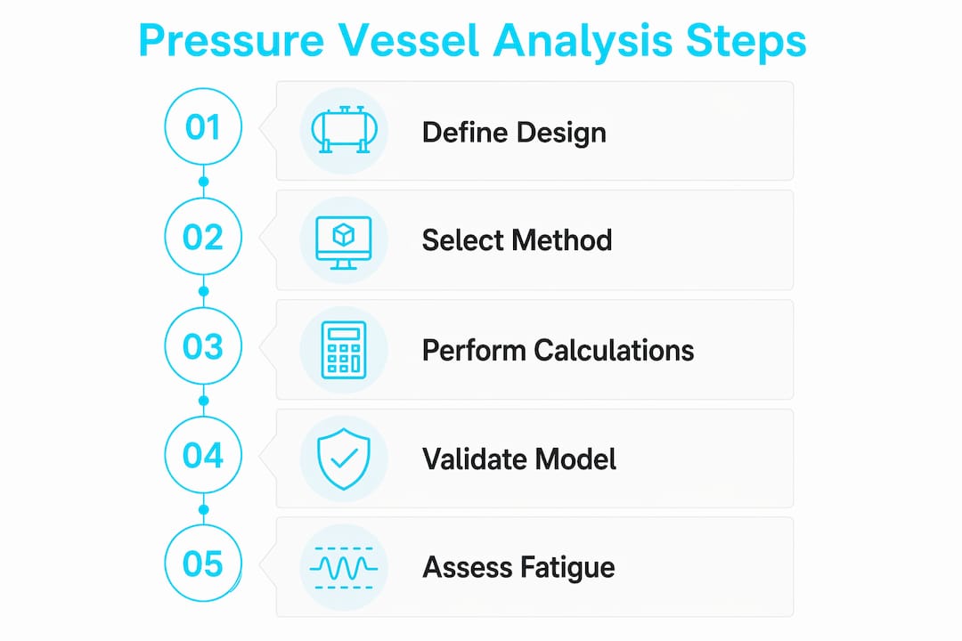
A compliant FEA-based analysis follows a defined sequence. Skipping steps, especially verification, is how errors survive to the final report.
Define design conditions. Temperature, pressure (operating and design), external loads (wind, seismic, nozzle loads, water hammer), and load combinations. Document these before opening the FEA preprocessor.
Geometry and simplification. Use axisymmetric 2D models for bodies of revolution without asymmetric loads; switch to 3D only when geometry or loading breaks symmetry. Remove features smaller than the mesh target size that do not affect the stress field of interest.
Select element types. For shells: quadratic shell elements (SHELL281 in ANSYS, or equivalent). For solid models: quadratic hexahedral or tetrahedral elements (SOLID186/187 in ANSYS). Linear elements underperform in bending-dominated regions.
Mesh strategy. Start coarse, then refine systematically. Use at least three elements through the wall thickness for solid models. Refine at nozzle fillets, weld toes, and head-to-shell junctions. Document element size and type at each region.
Boundary conditions. Apply symmetry conditions carefully; a misapplied symmetry plane introduces artificial stiffness. Constrain rigid-body motion without over-constraining the model. For thermal-mechanical coupling, apply temperature distributions from a separate thermal analysis or a coupled physics solve.
Load cases. Run each load case separately before combining: internal pressure, thermal gradient, seismic (response spectrum or time history), and water hammer (transient pressure pulse).
including thermal gradients and water hammer cannot be captured reliably by simple closed-form equations; physics-based simulation is the appropriate tool. 7. Nonlinearity and contact. For elastic-plastic checks, use a bilinear or multilinear true stress-strain curve. For bolted flanges or mating surfaces, define contact pairs with appropriate friction coefficients. Geometric nonlinearity (large displacement) is needed when deflections exceed roughly 10% of a characteristic dimension. 8. Solve and post-process. Extract stress linearization results along SCLs at every critical location. Separate P_m, P_L, P_b, Q, and F components. Compare each to the appropriate ASME allowable.
FEA verification checklist
Mesh convergence: refine the mesh in at least two steps and confirm that the peak stress change between refinements is less than 3% before accepting results. Document element type, size, and the convergence metric used.
Closed-form benchmark: for a simple cylindrical region, compare FEA hoop stress to the thin-wall or Lame formula. Agreement within 2–5% confirms the model is set up correctly.
Boundary-condition sensitivity: perturb support locations or stiffness slightly and confirm that global results are not sensitive to minor BC changes.
Load-case completeness: verify that every design load combination from step 1 has been run and that the governing combination has been identified.
Stress linearization check: confirm SCL orientations are perpendicular to the wall mid-surface and that the integration path spans the full thickness.
Pro Tip: When evaluating limit-load or collapse behavior, use an elastic-perfectly-plastic material model first (yield stress = 1.5× S_m per ASME Division 2 Annex 5-A) and apply load in incremental steps. Monitor the load-displacement curve; the limit load is the load at which the curve flattens. This approach sidesteps the stress-categorization problem entirely for gross plastic deformation checks.
For readers comparing FEA platforms, Jewlztech has a useful breakdown of ANSYS alternatives for vessel simulation workflows.
How do you handle nozzle and discontinuity stresses in practice?
Nozzles, cutouts, flange welds, and skirt attachments are where most pressure vessel failures initiate. The stress concentration at a nozzle intersection can be three to five times the nominal shell hoop stress, depending on the d/D ratio and the reinforcement geometry.
Typical discontinuities requiring screening:
Nozzle-to-shell intersections (radial, hillside, and oblique orientations)
Manway and handhole cutouts
Support lug and skirt attachment welds
Flange-to-shell junctions
Head-to-shell junctions (especially at the knuckle of a torispherical head)
Screening criteria: compute the area replacement ratio for each nozzle per ASME Section VIII Division 1 UG-37. If the available reinforcement area (from the shell and nozzle walls within the reinforcement zone) meets or exceeds the required area, the nozzle passes the DBR screen. If it does not, or if the nozzle is large (d/D > 0.5), local FEA is required.
For local FEA at nozzles: use a refined 3D solid model with at least four elements through the nozzle wall and the shell wall in the intersection region. Model the fillet weld geometry explicitly when fatigue is a concern. An axisymmetric model is acceptable for radial nozzles under pressure loading only; any out-of-plane moment or shear load from piping requires a full 3D model.
Document mesh density near fillets, the element type used, and the SCL locations selected for linearization. If the nozzle carries significant piping loads, include those as applied forces and moments at the nozzle flange face in addition to the internal pressure case.
How do you assess fatigue and cyclic loading in pressure vessels?
Fatigue governs design when a vessel experiences repeated pressure cycles, thermal transients, or start-stop loading. The S–N approach in ASME Section VIII Division 2 Annex 5-B uses design fatigue curves (stress amplitude vs. cycles to failure) derived from smooth-bar test data with built-in safety factors.
Stress range extraction from FEA:
The relevant quantity is the alternating stress intensity S_alt, defined as half the range of the maximum principal stress difference over a complete cycle:
S_alt = ΔS_ij,max / 2
where ΔS_ij is the range of the stress intensity (maximum principal stress difference) between the peak and valley of the load cycle. Extract this from FEA by running both the peak and valley load cases and computing the difference field.
Rainflow counting and Miner’s rule:
For vessels with multiple load types (pressure cycling, thermal transients, and occasional seismic events), the load history is not a simple sinusoid. Rainflow counting decomposes the stress-time history into individual cycles, each with its own amplitude and mean stress. Cumulative damage follows Miner’s rule:
D = Σ (n_i / N_i)
where n_i is the number of applied cycles at stress amplitude i and N_i is the allowable cycles from the S–N curve at that amplitude. Failure is predicted when D ≥ 1.0. ASME Division 2 requires D ≤ 1.0 with the design fatigue curves already incorporating a safety factor of 2 on stress and 20 on cycles (whichever is more conservative).
When fatigue drives the design:
Nozzles on cyclic storage vessels (daily fill-and-drain service)
Thin-walled vessels in thermal cycling service (heat exchangers, reactors)
Any location where the peak stress intensity exceeds 2S_m, triggering mandatory fatigue screening per Division 2
Mean-stress correction matters when the mean stress is a significant fraction of the ultimate tensile strength. The Goodman correction is conservative and widely accepted for carbon and low-alloy steels; the Gerber parabola is less conservative and may be appropriate for high-cycle regimes where test data supports it.
Worked numeric examples: thin cylinder and thick-wall Lame calculation
Example 1: Thin-walled cylindrical vessel
Given: Internal pressure P = 1.5 MPa, inside diameter D = 800 mm, wall thickness t = 20 mm.
Check thin-wall criterion: t / D = 20 / 800 = 0.025. Since 0.025 < 0.05 (i.e., t < D/20), the thin-wall assumption is valid.
Mean radius: R = (D/2) + (t/2) = 400 + 10 = 410 mm = 0.410 m.
Hoop stress: σ_θ = PR / t = (1.5 × 10⁶ × 0.410) / 0.020 = 30.75 MPa
Axial stress (closed ends): σ_a = PR / 2t = 30.75 / 2 = 15.38 MPa
Interpretation: Hoop stress governs. For SA-516 Grade 70 carbon steel, the ASME allowable stress S at room temperature is approximately 138 MPa (from ASME Section II Part D tables). The utilization ratio is 30.75 / 138 = 0.22, leaving substantial margin. If you model this in ANSYS or SolidWorks Simulation with a 2D axisymmetric shell, the FEA hoop stress should match within 2% of 30.75 MPa; any larger deviation signals a modeling error.
Example 2: Thick-walled cylinder using Lame’s equations
Given: Inner radius a = 50 mm, outer radius b = 100 mm, internal pressure P_i = 60 MPa, external pressure P_o = 0.
Compute constants:
A = (a²P_i − b²P_o) / (b² − a²) = (2500 × 60 − 10000 × 0) / (10000 − 2500) = 150,000 / 7500 = 20 MPa
B = a²b²(P_i − P_o) / (b² − a²) = (2500 × 10000 × 60) / 7500 = 1,500,000,000 / 7500 = 200,000 MPa·mm²
Stresses at inner wall (r = a = 50 mm):
σ_r = A − B/a² = 20 − 200,000/2500 = 20 − 80 = −60 MPa (compressive, equals −P_i ✓)
σ_θ = A + B/a² = 20 + 80 = 100 MPa (tensile, maximum hoop stress)
Stresses at outer wall (r = b = 100 mm):
σ_r = A − B/b² = 20 − 200,000/10000 = 20 − 20 = 0 MPa (equals −P_o = 0 ✓)
σ_θ = A + B/b² = 20 + 20 = 40 MPa
Worst-case location: inner wall, where σ_θ = 100 MPa and σ_r = −60 MPa. The von Mises equivalent stress at the inner wall (with axial stress σ_a = A = 20 MPa) is:
σ_VM = √[(σ_θ − σ_r)² + (σ_r − σ_a)² + (σ_a − σ_θ)²] / √2 = √[(160)² + (−80)² + (−80)²] / √2 ≈ 131 MPa
FEA cross-check: build a 2D axisymmetric model with quadratic elements, apply P_i = 60 MPa at the inner surface, and confirm that the hoop stress at the inner wall node matches 100 MPa within 2–3%. If you use a coarse single-layer mesh, expect the centroidal value to be slightly lower than the nodal peak; refine to at least three elements through the wall to capture the gradient correctly.
How do material properties and temperature affect allowable stresses?
Material selection sets the ceiling on every stress calculation. The wrong material choice, or ignoring temperature-dependent property changes, can invalidate an otherwise correct analysis.
Key selection criteria:
Yield and tensile strength at design temperature: ASME allowable stress S is derived from the lower of (yield strength / 1.5) and (tensile strength / 3.5) at temperature. Both values drop with increasing temperature.
Toughness and brittle fracture risk: carbon steels below their ductile-to-brittle transition temperature (DBTT) can fail at stresses well below yield. ASME requires impact testing (Charpy V-notch) for vessels operating below −20°F (−29°C) unless exempted by material curve and thickness.
Creep limits at elevated temperature: above roughly 700°F (371°C) for carbon steel and 1000°F (538°C) for austenitic stainless steel, creep governs. ASME allowable stresses in the creep regime are time-dependent and must be taken from the appropriate temperature row in Section II Part D tables.
Weld joint efficiency E: values of 1.0 (full radiography), 0.85 (spot radiography), or 0.70 (no radiography) multiply the allowable stress in thickness calculations. Using E = 1.0 without the required examination is a code violation.
Corrosion allowance (CA): the nominal wall thickness t_nominal = t_required + CA. The CA does not contribute to structural capacity; stress calculations use t_required only.
For thermal-mechanical FEA, temperature-dependent elastic modulus E(T), thermal expansion coefficient α(T), and yield stress σ_y(T) must all be entered as tabular material data. Using room-temperature properties in a high-temperature analysis is one of the most common and consequential modeling errors. The heat transfer techniques involved in conduction, convection, and radiation modeling directly affect the temperature distribution that feeds into thermal stress calculations.
ASME Section II Part D is the authoritative source for allowable stress values. Do not use handbook values or manufacturer data sheets as substitutes for code-tabulated allowables in a formal ASME submission.
How do you validate a pressure vessel FEA model experimentally?
Simulation confidence comes from comparison to physical measurements. For critical or safety-classified vessels, combining experimental stress analysis with FEA is standard industrial practice.
Validation checklist:
Select measurement locations at the highest predicted stress points (inner-wall nozzle junction, head knuckle, skirt attachment) and at a low-stress reference location for baseline verification.
Instrument choice: electrical resistance strain gauges (single-axis or rosette) for surface strains; rosettes are required wherever the principal stress directions are unknown. Gauge factor and temperature compensation must be matched to the vessel material.
Loading schedule: pressurize in at least three incremental steps (e.g., 25%, 50%, 75%, and 100% of design pressure) and record strain at each step. Linearity of the strain-pressure response confirms elastic behavior and catches any gauge malfunction.
Acceptance criteria for model-to-test agreement: a typical acceptance band for elastic FEA-to-gauge comparison is ±10–15% on principal strain magnitude at well-instrumented locations remote from welds. Locations near weld toes or geometric discontinuities may show larger scatter due to local residual stresses.
Pro Tip: Document every conservative assumption in the analysis report: material property lower bounds, corrosion allowance deducted from t, weld joint efficiency used, and any geometric simplification. When the model overpredicts measured strains by more than 15%, investigate boundary conditions and material properties before adjusting the model to fit the data. Fitting the model to test data without a physical justification is calibration, not validation.
For elastic-plastic or limit-load analyses, use experimental load-displacement data (from a hydrostatic proof test or a dedicated test specimen) to tune the true stress-strain curve. A coupon tensile test gives the engineering stress-strain curve; convert it to true stress-strain (σ_true = σ_eng(1 + ε_eng)) before entering it into the FEA material model.
Key Takeaways
Rigorous pressure vessel stress analysis requires matching the right method (thin-wall formulas, Lame’s equations, or FEA-based DBA) to the geometry and loading, then verifying results against ASME allowables and physical benchmarks.
Point | Details |
Thin-wall vs. Lame threshold | Use thin-wall formulas when t < D/20; switch to Lame’s equations when the wall is thicker or radial stress matters. |
DBA pressure advantage | Design-by-analysis can yield allowable pressures roughly 2.3 to 3 times higher than design-by-rule for the same material and geometry, depending on the material and standard. |
Stress classification is critical | Misclassifying secondary stresses as primary forces overdesign; always linearize FEA results along a defined SCL before comparing to ASME allowables. |
Mesh convergence standard | Confirm peak stress change between mesh refinements is less than 3% and document element type, size, and convergence metric before sign-off. |
Jewlztech Thermalysis Toolkit | The Thermalysis Toolkit supports combined thermal and mechanical parametric runs with a built-in property database, accelerating closed-form checks and FEA pre-processing. |
Why the conventional wisdom on FEA for pressure vessels gets it backwards
Most engineers treat FEA as the answer and hand calculations as the check. The workflow should run the other way. A closed-form Lame solution or a thin-wall membrane check takes ten minutes and immediately tells you the order of magnitude of the governing stress. If your FEA result is off by a factor of two from that estimate, you have a modeling error, not a surprising result. Running FEA first and then trying to explain why the numbers look odd is how projects lose weeks.
The second thing practitioners underestimate is how much the stress classification step matters relative to the FEA itself. You can have a beautifully converged, well-validated finite element model and still produce a non-compliant Division 2 submission if the SCL locations are poorly chosen or the membrane-bending decomposition is done carelessly. The code does not care how fine your mesh is; it cares whether P_m is below S and whether Q + F satisfies the shakedown criterion. Those are post-processing decisions, not solver decisions.
There is also a project-level trade-off that rarely gets discussed openly: Division 2 DBA costs more upfront in engineering hours but often pays back in material savings and reduced fabrication cost on large vessels. The break-even point depends on vessel size, material cost, and how many nozzles need local analysis. For a small vessel under 500 gallons, DBR is almost always the right call. For a large reactor vessel or a high-pressure heat exchanger, the DBA investment typically recovers its cost in the first order. Present that trade-off to stakeholders with numbers, not just a recommendation, and you will get a faster decision.
The Thermalysis Toolkit by Jewlztech accelerates your vessel calculations
Running combined thermal and mechanical analyses on pressure vessels means managing temperature-dependent material properties, multiple heat transfer modes, and parametric geometry variations simultaneously. That is exactly what the Thermalysis Toolkit is built for.

The toolkit is an Excel-based physics simulation environment that handles conduction, convection, and radiation in a single model, with a built-in material property database that covers the temperature ranges relevant to ASME vessel design. You can run closed-form parametric checks (varying wall thickness, operating temperature, or pressure in seconds), export results directly into your engineering report, and use the property database to populate temperature-dependent inputs for your FEA model without hunting through Section II Part D tables manually.
For engineers working through the FEA workflow described in this guide, the Thermalysis Toolkit fits naturally at the pre-processing stage: confirm your thermal boundary conditions and material property selections before committing to a full FEA run. It also works as a fast sanity check after FEA, letting you verify that the thermal stress magnitudes your model produces are in the right range for the temperature gradient and material combination you specified. Visit the Thermalysis Toolkit product page to explore the full feature set and download options.
Authoritative sources and references to consult next
The analysis methods in this guide draw from the following primary references. Use them for code clause citations, deeper derivations, and Division 2 documentation requirements.
ASME BPVC Section VIII and supporting guidebook The Guidebook for the Design of ASME Section VIII Pressure Vessels (ASME Press, Fourth Edition) is the most practical companion to the code itself. It provides worked examples for both Division 1 and Division 2, stress category definitions, and documentation templates for DBA submissions. Any formal ASME submission should cite specific clause numbers from the current edition of the code, not secondary sources.
Air Force Stress Analysis Manual (thin-vessel sections) The thin-pressure-vessel sections of the Air Force Stress Manual cover membrane formulas for cylinders, spheres, and common heads, plus junction and discontinuity calculations. It remains one of the most complete hand-calculation references for membrane and head stress work and is freely available through engineering library repositories.
NAfems pressure vessel stress knowledge base The NAfems knowledge base on pressure vessel stresses covers stress classification, linearization procedures, and the practical challenges of applying ASME allowable criteria to FEA results. It is particularly useful for understanding the primary-vs-secondary classification problem and the role of elastic-plastic analysis in DBA.
Engineering LibreTexts: General Stress Analysis The Engineering LibreTexts stress analysis module/05%3A_General_Stress_Analysis) covers closed-form solutions, experimental methods, and FEA fundamentals at a level appropriate for senior undergraduates and early-career engineers. It is a reliable starting point for students building toward the more advanced ASME-specific material.
ResearchGate: DBA pressure vessel study The DBA study on ResearchGate quantifies the pressure advantage of DBA over DBR and provides a worked comparison useful for justifying the DBA route to stakeholders or in a design report.
Jewlztech pressure vessel design software guide For a practical comparison of simulation tools that support the workflow described here, the Jewlztech guide to pressure vessel design software alternatives covers Excel-based toolkits and FEA packages relevant to engineers working within ASME frameworks.
Recommended
Comments