
TPMS Structure: A Technical Guide for Engineers


A TPMS structure is defined as the integrated assembly of pressure sensors, signal processing electronics, wireless communication modules, and an in-vehicle receiver that monitors tire pressure in real time. The industry standard term is “tire pressure monitoring system,” and its architecture divides into two distinct categories: direct TPMS and indirect TPMS. Direct TPMS uses a physical sensor in each wheel containing a MEMS pressure transducer, temperature sensor, accelerometer, lithium-based battery, and RF transmitter. Indirect TPMS relies on ABS wheel speed sensors and onboard algorithms to infer pressure changes without any hardware inside the wheel. Understanding this distinction is the foundation for every design, validation, and maintenance decision in TPMS engineering.
What is the TPMS structure of a direct sensor?
Direct TPMS sensors carry the full measurement burden inside a single, wheel-mounted module. Each module must survive continuous vibration, wide temperature swings, and chemical exposure while transmitting accurate pressure data to the vehicle ECU. The structural design of this module is not arbitrary. Every component serves a specific function within a tightly constrained power and space budget.
Pressure transducer
The core sensing element is a MEMS piezoresistive transducer built around a silicon diaphragm with embedded strain gauges. When tire pressure deflects the diaphragm, the strain gauges change resistance in proportion to the applied force. This resistance change converts to a voltage signal, which the onboard ADC digitizes. Resolution requirements for automotive-grade sensors are better than 0.05 bar, which demands careful amplifier design and low-noise layout.

Temperature sensor and accelerometer
An integrated temperature sensor sits adjacent to the pressure element and serves two roles. First, it compensates for the thermal sensitivity of the piezoresistive element, which shifts its output across the operating range of roughly -40°C to 125°C. Second, it provides a direct temperature warning to the driver when tire heat exceeds safe limits. The accelerometer detects wheel rotation. When the wheel is stationary, the accelerometer suppresses transmission to conserve battery power. Once rotation begins, the module wakes up and starts its sampling cycle.
Battery, RF transmitter, and housing
Lithium-based sealed battery: Powers the module for the vehicle’s service life, typically 5–10 years, but is not field-replaceable. Battery depletion forces full sensor replacement.
RF transmitter: Broadcasts pressure and temperature data at 315 MHz or 433 MHz depending on regional market requirements. The antenna layout inside the housing directly affects link reliability.
Valve stem design: Metal valve stems offer greater durability against UV exposure and road chemicals. Rubber stems are easier to install but degrade faster, often failing before the electronics do.
Protective housing: Molded polymer or metal caps enclose the PCB and sensor die. The package must pass salt spray, shock, and thermal cycling qualification tests per automotive standards.
Pro Tip: When specifying a direct TPMS sensor for a new platform, select metal valve stems from the start. Rubber stems are a common source of early field returns that have nothing to do with sensor electronics.
How do direct and indirect TPMS systems differ in structure?
The structural difference between direct and indirect TPMS is fundamental, not incremental. Direct systems add hardware inside each wheel. Indirect systems repurpose existing ABS infrastructure and add software.
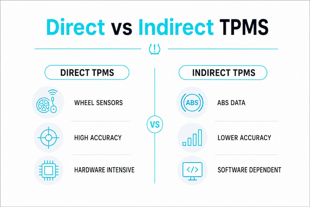
Feature | Direct TPMS | Indirect TPMS |
Sensing hardware | Wheel-mounted sensor module per tire | No additional wheel hardware |
Pressure output | Real-time PSI per tire | General warning only |
Accuracy | ~1–2 PSI per tire | Cannot report absolute PSI |
Equal deflation detection | Yes, per-wheel | No, misses all-four-tire deflation |
Maintenance requirement | Sensor relearn after rotation or replacement | Recalibration after tire service |
Cost and complexity | Higher hardware cost | Lower hardware cost, higher software dependency |
Direct TPMS provides per-tire pressure and temperature data with approximately 1–2 PSI accuracy, working at rest or in motion depending on the sensor design. That level of granularity is what regulators in the United States and European Union require for new vehicle type approval.
Indirect TPMS has one structural blind spot that engineers must understand clearly. Indirect systems cannot detect pressure loss when all four tires deflate equally, because the ABS algorithm compares relative wheel speeds. Equal deflation produces no speed differential, so the system reports no fault. This is not a software bug. It is a structural limitation of the indirect architecture.
From a maintenance standpoint, direct TPMS demands more from service technicians. Tire professionals must perform sensor relearn sequences to pair each sensor’s unique ID with the vehicle ECU after any rotation or replacement. Indirect systems require only a recalibration reset, which takes seconds. Automotive engineering guidance confirms that direct TPMS delivers precision but carries higher maintenance complexity from valve stem sealing and sensor fatigue.
What signal processing techniques improve TPMS accuracy and leak detection?
Raw sensor output from a MEMS transducer is noisy. Thermal drift, mechanical vibration, and electromagnetic interference all corrupt the pressure signal before it reaches the ECU. The TPMS architecture addresses this through a layered signal processing chain embedded in the sensor module’s firmware.
High-resolution ADC conversion. Modern direct TPMS modules use 24-bit ADCs to digitize the analog pressure signal. A 24-bit converter provides over 16 million discrete levels across the measurement range, which is far more than needed for display purposes but critical for detecting slow leaks that change pressure by only a few millibar per hour.
Temperature compensation via lookup tables. The firmware stores a calibration table mapping temperature to pressure offset corrections. At each sampling interval, the module reads the temperature sensor and applies the corresponding correction before reporting pressure. This eliminates the systematic error introduced by the piezoresistive element’s thermal sensitivity.
Kalman filter for state estimation. Kalman filters predict tire pressure states using temperature and driving inputs, then update those predictions with each new sensor measurement. The filter separates true pressure changes from measurement noise by weighting predictions and observations according to their respective uncertainties. The result is a smoothed, reliable pressure estimate even on rough road surfaces.
CUSUM algorithm for leak detection. The cumulative sum algorithm accumulates small residual drifts between predicted and measured pressure over time. When the cumulative sum crosses a preset threshold, the system flags a slow leak. This approach catches gradual pressure loss that a simple threshold comparison would miss entirely.
Digital low-pass filtering. A digital filter removes high-frequency noise from road vibration before the Kalman filter processes the signal. The cutoff frequency is tuned to pass pressure dynamics while rejecting mechanical interference.
Achieving the required resolution in a TPMS sensor involves not only sensor design but also a sophisticated signal chain: high-resolution ADCs, temperature compensation, and digital filtering to handle MEMS drift across wide temperature ranges. The hardware and the algorithm are inseparable parts of the same measurement system.
What practical challenges affect TPMS sensor durability and integration?
The TPMS architecture looks clean on paper. In the field, engineers encounter a set of durability and integration challenges that do not appear in datasheets.
Valve stem degradation. Rubber valve stems degrade from UV exposure, road chemicals, and repeated flexing. The rubber can crumble before the sensor electronics fail, forcing a full sensor replacement even when the pressure transducer and battery are still functional. Metal stems cost more but eliminate this failure mode.
Battery life constraints. The sealed lithium battery is the sensor’s hard lifetime limit. Power management in active TPMS modules uses low-power wake-up triggers from the accelerometer and event-driven sampling to extend battery life. Firmware must interleave pressure sampling with acceleration detection to avoid exceeding detection time limits while minimizing current draw.
Thermal cycling fatigue. Sensors mounted inside a tire experience temperature swings from below freezing in winter to over 100°C during high-speed driving. Solder joints, bond wires, and the sensor die itself accumulate fatigue damage over thousands of cycles. Reliability-oriented TPMS design now applies physics-driven machine learning models to balance geometric precision, manufacturability, and defect tolerance under thermal stress.
Sensor relearn complexity. After any tire rotation or sensor replacement, the vehicle ECU must learn the new sensor IDs. This process requires either a dedicated scan tool, a magnet activation sequence, or an automatic relearn drive cycle depending on the vehicle platform. Each approach adds time and cost to routine tire service.
Vibration and moisture ingress. The sensor housing must maintain its seal integrity across the full service life. Poorly specified gaskets or inadequate potting compound allow moisture to reach the PCB, causing corrosion and signal drift.
Pro Tip: During design validation, run your TPMS sensor through at least 1,000 thermal cycles before finalizing the housing material and potting compound. Field failures from thermal fatigue almost always trace back to shortcuts in this phase.
Key Takeaways
A direct TPMS structure integrates MEMS pressure transducers, temperature sensors, accelerometers, sealed lithium batteries, and RF transmitters into a single wheel-mounted module that delivers real-time, per-tire PSI data to the vehicle ECU.
Point | Details |
Direct vs. indirect architecture | Direct TPMS uses wheel-mounted sensors for per-tire PSI; indirect uses ABS speed data and misses equal deflation events. |
Signal processing chain | 24-bit ADCs, Kalman filters, and CUSUM algorithms work together to detect slow leaks amid noise and thermal drift. |
Valve stem selection | Metal valve stems outlast rubber stems and prevent premature sensor replacement unrelated to electronics failure. |
Battery and power management | Accelerometer-triggered wake-up and event-driven sampling extend sealed battery life across the vehicle service period. |
Reliability under stress | Physics-driven modeling and thorough thermal cycling validation are required to achieve durability across real operating conditions. |
TPMS structural design: what the field actually teaches you
The textbook version of TPMS architecture makes the system look like a solved problem. Four sensors, one receiver, a few algorithms. Done. The reality is that most field failures in TPMS do not come from the pressure transducer. They come from the parts that surround it.
Valve stems, potting compounds, and solder joint geometry account for a disproportionate share of warranty returns. I have seen programs where the sensor die performed flawlessly in lab testing, but the housing failed within two winters because the potting compound was not specified for the actual temperature range the tire sees during highway driving. The datasheet said it was fine. The road said otherwise.
The growing use of machine learning in TPMS reliability modeling is genuinely useful, but only when it is fed real environmental data. Models trained on idealized load cases produce optimistic predictions. Engineers who instrument test vehicles and capture actual thermal and vibration profiles get models that predict field behavior accurately. That gap between lab and field is where most reliability problems hide.
The other trend worth watching is the shift toward Bluetooth Low Energy for sensor communication. Proprietary 315 MHz and 433 MHz links are mature and well understood, but BLE opens the door to smartphone integration and over-the-air firmware updates. The structural implications are real: BLE stacks consume more power than simple RF transmitters, which puts additional pressure on the already constrained battery budget. Any engineer evaluating BLE-based TPMS needs to model the power budget before committing to the architecture, not after.
The interdisciplinary nature of TPMS design is its defining challenge. Mechanical engineers own the housing and valve stem. Electrical engineers own the sensor and signal chain. Firmware engineers own the algorithms. When those three groups do not share a common reliability target from day one, the system pays for it in the field.
— Joel
Jewlztech tools for TPMS sensor analysis and validation
Engineers working on TPMS sensor design and signal processing need tools that handle both thermal analysis and pressure data refinement in a single workflow.

The Thermalysis Toolkit from Jewlztech supports thermal simulation and sensor performance analysis directly relevant to TPMS development. It helps engineers model the thermal environment inside a wheel assembly, validate temperature compensation strategies, and refine signal processing algorithms like CUSUM-based leak detection. The toolkit integrates with existing engineering workflows without requiring a separate simulation environment. For automotive engineers validating TPMS sensor designs against real operating conditions, Jewlztech’s thermal simulation capabilities provide a structured path from design to verified performance.
FAQ
What is the basic structure of a direct TPMS sensor?
A direct TPMS sensor contains a MEMS pressure transducer, temperature sensor, accelerometer, sealed lithium battery, and RF transmitter housed in a protective module mounted inside the wheel. These components work together to measure, process, and transmit tire pressure data to the vehicle ECU.
Why can’t indirect TPMS detect equal pressure loss in all four tires?
Indirect TPMS infers pressure changes from differences in ABS wheel speed data. When all four tires lose pressure equally, no speed differential exists between wheels, so the algorithm detects no fault.
How does a Kalman filter improve TPMS pressure measurement?
A Kalman filter estimates the true tire pressure state by combining a physics-based prediction with each new sensor measurement, weighted by their respective uncertainties. This separates genuine pressure changes from measurement noise caused by road vibration and thermal drift.
What causes most TPMS sensor failures in the field?
Valve stem degradation and battery depletion are the leading causes of TPMS sensor replacement. Rubber valve stems degrade from UV exposure and road chemicals, often failing before the sensor electronics reach end of life.
What transmission frequencies do TPMS sensors use?
TPMS sensors transmit at 315 MHz in North America and 433 MHz in most other markets, with antenna layout inside the sensor housing tuned to maintain reliable wireless communication to the vehicle receiver.
Recommended
Comments